opengl draw points in 3d
This chapter is from the volume
Drawing Lines in 3D
The GL_POINTS primitive we accept been using thus far is reasonably straightforward; for each vertex specified, it draws a signal. The next logical stride is to specify ii vertices and draw a line betwixt them. This is exactly what the side by side primitive, GL_LINES, does. The following brusk section of code draws a single line between two points (0,0,0) and (50,50,l):
glBegin(GL_LINES); glVertex3f(0.0f, 0.0f, 0.0f); glVertex3f(50.0f, 50.0f, fifty.0f); glEnd();
Note here that ii vertices specify a single archaic. For every two vertices specified, a single line is drawn. If you specify an odd number of vertices for GL_LINES, the last vertex is just ignored. Listing 3.four, from the LINES sample program on the CD, shows a more circuitous sample that draws a series of lines fanned around in a circle. Each bespeak specified in this sample is paired with a point on the contrary side of a circle. The output from this program is shown in Figure three.vi.
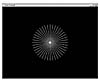 Effigy 3.6 Output from the LINES sample program.
List 3.4 Code from the Sample Plan LINES That Displays a Series of Lines Fanned in a Circle
// Call only once for all remaining points glBegin(GL_LINES); // All lines lie in the xy aeroplane. z = 0.0f; for(angle = 0.0f; angle <= GL_PI; angle += (GL_PI/xx.0f)) { // Top one-half of the circle x = 50.0f*sin(angle); y = 50.0f*cos(angle); glVertex3f(x, y, z); // Outset endpoint of line // Bottom half of the circle x = 50.0f*sin(angle + GL_PI); y = fifty.0f*cos(bending + GL_PI); glVertex3f(10, y, z); // 2d endpoint of line } // Done drawing points glEnd(); Line Strips and Loops
The next two OpenGL primitives build on GL_LINES by assuasive y'all to specify a list of vertices through which a line is drawn. When you specify GL_LINE_STRIP, a line is drawn from one vertex to the adjacent in a continuous segment. The following code draws ii lines in the xy plane that are specified by three vertices. Effigy three.7 shows an example.
glBegin(GL_LINE_STRIP); glVertex3f(0.0f, 0.0f, 0.0f); // V0 glVertex3f(l.0f, 50.0f, 0.0f); // V1 glVertex3f(l.0f, 100.0f, 0.0f); // V2 glEnd();
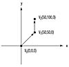 Figure 3.seven An example of a GL_LINE_STRIP specified by three vertices.
The last line-based archaic is GL_LINE_LOOP. This archaic behaves just like GL_LINE_STRIP, but ane final line is fatigued between the final vertex specified and the first one specified. This is an like shooting fish in a barrel way to describe a closed-line figure. Figure three.eight shows a GL_LINE_LOOP drawn using the same vertices every bit for the GL_LINE_STRIP in Figure 3.seven.
Approximating Curves with Straight Lines
The POINTS sample programme, shown earlier in Figure 3.3, showed you lot how to plot points along a spring-shaped path. You might have been tempted to button the points closer and closer together (by setting smaller values for the angle increase) to create a shine spring-shaped curve instead of the broken points that only approximated the shape. This perfectly valid performance can movement quite slowly for larger and more complex curves with thousands of points.
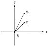 Figure 3.viii The aforementioned vertices from Effigy iii.vii used by a GL_LINE_LOOP primitive.
A better way of approximating a bend is to use GL_LINE_STRIP to play connect-the-dots. As the dots move closer together, a smoother curve materializes without your having to specify all those points. Listing 3.5 shows the code from Listing 3.2, with GL_POINTS replaced by GL_LINE_STRIP. The output from this new program, LSTRIPS, is shown in Effigy 3.nine. As you lot tin see, the approximation of the curve is quite good. You will find this handy technique almost ubiquitous amidst OpenGL programs.
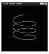 Figure 3.9 Output from the LSTRIPS programme approximating a smooth curve.
Listing iii.5 Code from the Sample Program LSTRIPS, Demonstrating Line Strips
// Phone call merely one time for all remaining points glBegin(GL_LINE_STRIP); z = -50.0f; for(angle = 0.0f; angle <= (two.0f*GL_PI)*3.0f; angle += 0.1f) { x = 50.0f*sin(angle); y = 50.0f*cos(angle); // Specify the bespeak and move the z value up a little glVertex3f(x, y, z); z += 0.5f; } // Done cartoon points glEnd(); Setting the Line Width
Just equally you lot can set dissimilar point sizes, you can as well specify diverse line widths when drawing lines by using the glLineWidth role:
void glLineWidth(GLfloat width);
The glLineWidth role takes a single parameter that specifies the gauge width, in pixels, of the line drawn. Simply like point sizes, not all line widths are supported, and you should make sure the line width you desire to specify is available. Use the following code to become the range of line widths and the smallest interval between them:
GLfloat sizes[2]; // Shop supported line width range GLfloat stride; // Store supported line width increments // Get supported line width range and pace size glGetFloatv(GL_LINE_WIDTH_RANGE,sizes); glGetFloatv(GL_LINE_WIDTH_GRANULARITY,&stride);
Here, the sizes array volition comprise two elements that contain the smallest and largest valid value for glLineWidth. In add-on, the variable pace will agree the smallest step size allowable betwixt the line widths. The OpenGL specification requires only that one line width, ane.0, be supported. The Microsoft implementation of OpenGL allows for line widths from 0.5 to 10.0, with 0.125 the smallest step size.
Listing iii.6 shows code for a more than substantial instance of glLineWidth. Information technology'southward from the programme LINESW and draws 10 lines of varying widths. Information technology starts at the bottom of the window at –90 on the y-axis and climbs the y-axis 20 units for each new line. Every fourth dimension it draws a new line, it increases the line width by one. Figure 3.10 shows the output for this program.
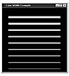 Figure 3.10 Demonstration of glLineWidth from the LINESW program.
Listing 3.6 Drawing Lines of Various Widths
// Called to draw scene void RenderScene(void) { GLfloat y; // Storage for varying Y coordinate GLfloat fSizes[two]; // Line width range metrics GLfloat fCurrSize; // Save current size ... ... ... // Get line size metrics and relieve the smallest value glGetFloatv(GL_LINE_WIDTH_RANGE,fSizes); fCurrSize = fSizes[0]; // Step up y axis 20 units at a fourth dimension for(y = -90.0f; y < 90.0f; y += xx.0f) { // Set the line width glLineWidth(fCurrSize); // Draw the line glBegin(GL_LINES); glVertex2f(-fourscore.0f, y); glVertex2f(80.0f, y); glEnd(); // Increase the line width fCurrSize += 1.0f; } ... ... } Notice that we used glVertex2f this time instead of glVertex3f to specify the coordinates for the lines. Every bit mentioned, using this technique is only a convenience because we are cartoon in the xy aeroplane, with a z value of 0. To see that y'all are still drawing lines in three dimensions, merely use the arrow keys to spin your lines around. You hands encounter that all the lines lie on a unmarried plane.
Line Stippling
In addition to changing line widths, you can create lines with a dotted or dashed blueprint, called stippling. To utilise line stippling, yous must showtime enable stippling with a call to
glEnable(GL_LINE_STIPPLE);
And so the role glLineStipple establishes the pattern that the lines use for cartoon:
void glLineStipple(GLint factor, GLushort pattern);
Reminder
Any feature or ability that is enabled by a phone call to glEnable tin be disabled by a call to glDisable.
The pattern parameter is a 16-bit value that specifies a pattern to use when cartoon the lines. Each flake represents a section of the line segment that is either on or off. By default, each bit corresponds to a single pixel, but the cistron parameter serves every bit a multiplier to increase the width of the pattern. For example, setting gene to v causes each bit in the blueprint to correspond v pixels in a row that are either on or off. Furthermore, bit 0 (the to the lowest degree significant bit) of the pattern is used kickoff to specify the line. Figure 3.xi illustrates a sample flake pattern applied to a line segment.
Why Are These Patterns Backward?
Y'all might wonder why the bit design for stippling is used in reverse when drawing the line. Internally, information technology's much faster for OpenGL to shift this pattern to the left one identify each time it needs to get the next mask value. OpenGL was designed for loftier-performance graphics and frequently employs similar tricks elsewhere.
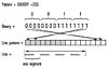 Figure iii.eleven A stipple pattern is used to construct a line segment.
Listing 3.7 shows a sample of using a stippling pattern that is just a series of alternate on and off bits (0101010101010101). This code is taken from the LSTIPPLE program, which draws 10 lines from the bottom of the window up the y-axis to the top. Each line is stippled with the blueprint 0x5555, but for each new line, the pattern multiplier is increased by one. Y'all can clearly come across the furnishings of the widened stipple blueprint in Figure 3.12.
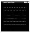 Effigy three.12 Output from the LSTIPPLE program.
Listing 3.seven Code from LSTIPPLE That Demonstrates the Event of factor on the Scrap Blueprint
// Chosen to draw scene void RenderScene(void) { GLfloat y; // Storage for varying y coordinate GLint factor = 1; // Stippling factor GLushort pattern = 0x5555; // Stipple pattern ... ... // Enable Stippling glEnable(GL_LINE_STIPPLE); // Stride upwards Y axis 20 units at a time for(y = -90.0f; y < 90.0f; y += twenty.0f) { // Reset the repeat factor and pattern glLineStipple(factor,pattern); // Describe the line glBegin(GL_LINES); glVertex2f(-80.0f, y); glVertex2f(80.0f, y); glEnd(); factor++; } ... ... } Merely the power to describe points and lines in 3D gives yous a meaning fix of tools for creating your own 3D masterpiece. I wrote the commercial awarding shown in Figure 3.13. Annotation that the OpenGL-rendered map is rendered entirely of solid and stippled line strips.
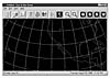 Effigy iii.xiii A 3D map rendered with solid and stippled lines.
lyonsbeetting1968.blogspot.com
Source: https://www.informit.com/articles/article.aspx?p=328646&seqNum=6
Post a Comment for "opengl draw points in 3d"